Modeling/Data Editor
Before building the model, it is important to know the coordinate system. Z-axis is the spinning axis in DyRoBeS. The lateral vibration of the discretized system is described by two translational (x, y) and two rotational  coordinates at each finite element station. For torsional vibration, the motion of each finite element station is described by a rotational displacement
  about the spinning axis. For axial vibration, the motion of each finite element station is described by a translational displacement (z) along the spinning axis.
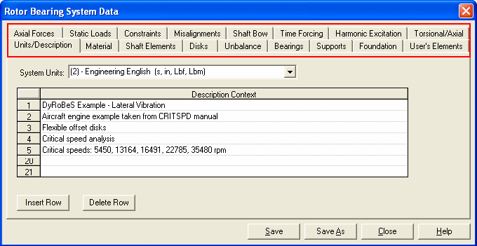
A number of folders, as shown below, with different tabs are provided in the Data Editor and you can enter your rotor bearing system data accordingly. The description for each folder will be explained in the following sessions.

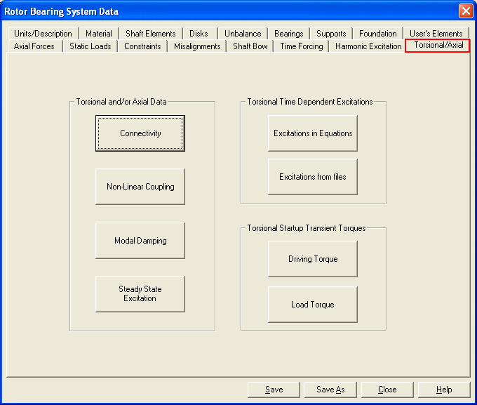
There are more tabs (buttons) under the Torsional/Axial Tab as shown below.

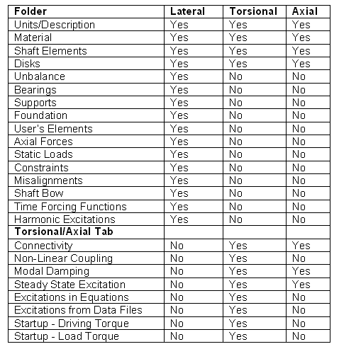
Since the same data file can be used in the lateral, torsional, and axial vibrations, data in the irrelevant folder will not be used in a particular analysis. The usage of the data folder is listed below for reference.
Data Utilization for Lateral, Torsional, and Axial Analysis

It should be noted that the same model will be used in lateral, torsional, and axial analyses, even though some of the inputs are not required for certain analyses and these entries will be ignored.
Since saving data is just a click on the Save button, it is a good practice to save your data from time to time to prevent any data loss. If you wish to save a different model without changing the original data, use Save As to save the data into another file,
See also:
Data Editor
Unit Systems
Description
Material
Shaft Elements
Rigid/Flexible Disks
Unbalance
Bearings and Seals
0-Linear constant bearing
1-Speed dependent bearing
2-Bearing coefficients from external data file
3-Pseudo bearing
4-Squeeze film damper
5-Plain journal bearing
6-Generalized non-linear isotropic bearing
7-Active magnetic bearing (Linear Model)
8-Active magnetic bearing (Nonlinear Model)
9-Floating ring bearing
10-General non-linear polynomial bearing
11-Liquid annular seal
12-Multi-Lobe hydrodynamic bearing (input data in Rotor)
13-Multi-Lobe hydrodynamic bearing (input data in BePerf)
14-Future implementation
Flexible Supports
Foundation
Userís Elements
Axial Force & Torque
Static Loads
Constraints
Misalignments
Shaft Bows
Time Forcing Functions
Harmonic Excitations
Torsional/Axial Data
Connectivity
Modal Damping
Non-Linear Connection/Coupling
Steady State Excitation
Time Dependent Torsional Excitations
Driving Torque
Load Torque
Engine Excitation
Reciprocating Excitation
Gear Mesh Data
Model Summary
Dyrobes Home |
Dyrobes Help Contents
Copyright © 2014-2017
 coordinates at each finite element station. For torsional vibration, the motion of each finite element station is described by a rotational displacement
  about the spinning axis. For axial vibration, the motion of each finite element station is described by a translational displacement (z) along the spinning axis.

