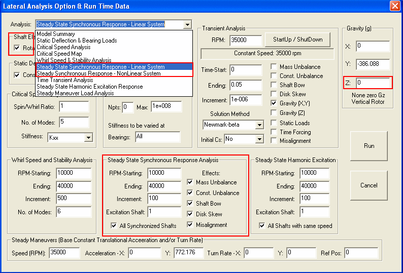
Steady State Synchronous Response Analysis
The Steady State Synchronous Response Analysis calculates the steady state synchronous response due to unbalance force (mass or/and magnet), shaft bow, disk skew, and misalignment for systems with Linear Bearings or with Non-Linear Isotropic Bearings (Bearing Type 4 - Squeeze Film Dampers, and Bearing Type 6 – general Non-Linear Isotropic Bearing). For linear systems, the response orbits are elliptical in general. However, for non-linear isotropic systems, centered circular orbits are assumed in the analysis. This analysis is commonly used to determine the rotor speeds that produce the peak response (separation margin) and the corresponding levels of vibration (amplification factor).
The shaft rotational speeds (starting, ending, and incremental speeds) are required in the run time data. For multiple shaft systems, the shaft speed is referred to the shaft number 1 speed. For single speed calculation, enter the speed as the starting speed and set the ending speed and incremental speed to zero. The Excitation Shaft indicates the shaft number to be considered with excitation for multi-shaft systems. The effects due to unbalance (mass or magnet), shaft bow, disk skew, and misalignment, can be included (box checked) or neglected (box unchecked). Note that if shaft bow and fitting method are given, then the disk skew due to shaft bow effect is added to the total disk skew. The check box for the All Synchronized Shafts is used if the excitations from all other shafts, which have the same rotational speed with the Excitation Shaft are also included in the analysis.
The output can be presented in many forms, such as, Bode plot, polar plot, elliptical orbit axes plot, bearing/support transmitted force, response at multiple stations, element shear forces and moments, shaft response and displacement orbit at specified speed. The relative displacement, velocity and acceleration are also available.

For sample outputs, click Steady State Response Plots.
Copyright © 2014-2017