Torsional/Axial Steady State Response
This option displays the torsional or axial steady state forced response and associated vibratory torque (force) and stress. For the torsional analysis, the results can be displayed in the equivalent coordinate or physical coordinate. For torsional vibration, the mass, stiffness, damping, and torque are converted into the equivalent mass, stiffness, damping, and torque referred to shaft 1 for analysis. However, the results can be displayed in either coordinate system. For details on this conversion, click Torsional Vibration Analysis. You can change the graph title, labels, scale, number of divisions and many others by changing the default settings in the Setting dialog under Options menu.
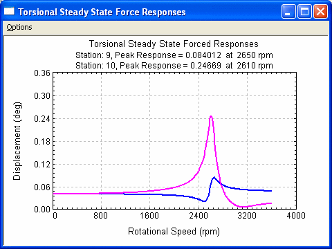
Figure shows the Displacements at stations 9 and 10

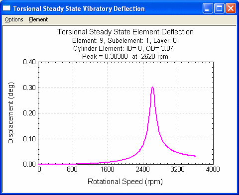
Figure shows the Deflection at Element 9 = abs(displacement 9 – displacement 10)
Torsional/Axial Vibratory Torque/Forces
This option displays the element vibratory torque (torsional vibration) or vibratory force (axial vibration). The results for multiple elements can be displayed in the same plot. Caution must be taken for multi-shaft systems since the element number does not exist for the last station of each shaft. For multi-shaft systems, the station numbers are consecutive and the element numbers are not continuous. See Shaft Elements session for better description. You can change the graph title, labels, scale, number of divisions and many others by changing the default settings in the Setting dialog under Options menu.
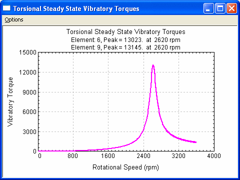
Multiple Vibratory Torques at Elements 6 and 9 (Element):
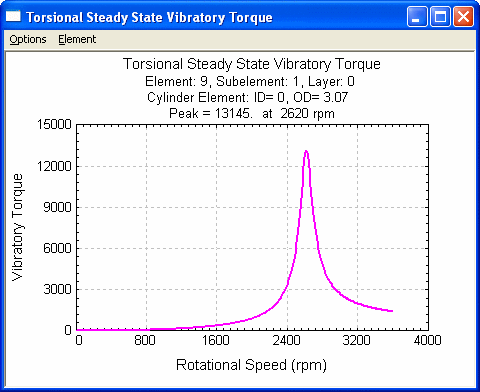
Vibratory Torque at Element 9, Subelement 1, Layer 0 (this option goes to the subelement level):
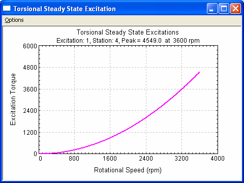
Torsional/Axial Steady State Excitations
This plot displays the steady state excitations used in the torsional or axial analysis. This is used to double-check the excitation input. Fore more information on the excitation, click Torsional Steady State Excitation. You can change the graph title, labels, scale, number of divisions and many others by changing the default settings in the Setting dialog under Options menu.
Excitation amplitude vs. speed
Torsional Vibratory Stress
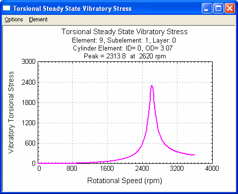
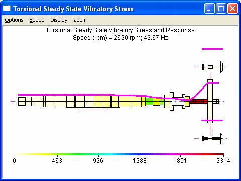
This option displays the element vibratory stress vs. speed or the element stress for a given speed. Caution must be taken for multi-shaft systems since the element number does not exist for the last station of each shaft. For multi-shaft systems, the station numbers are consecutive and the element numbers are not continuous. See Shaft Elements session for better description. You can change the graph title, labels, scale, number of divisions and many others by changing the default settings in the Setting dialog under Options menu.
Element 9 stress vs. speed
Element stresses at 2620 rpm
See also Torsional Vibration Analysis, Steady State Forced Response Analysis.
Copyright © 2014-2017