
Liquid Annular Seals Calculation
The liquid annular seals used in the pumps are known to raise the dry critical speeds by a considerable amount. Due to the pressure drop across the seal, the pressure difference develops a strong radial restoring force opposing to the shaft displacement. This effect is known as Lomakin effect. Black and Jenssen have extended Lomakin’s theory in the development of the rotordynamics coefficients by using the bulk flow analysis. Later Childs formulated a more complete bulk flow model using Hirs’ lubrication equation which includes the influence of fluid inertia terms and inlet swirl. For small motion, the forces generated in an annular seal are:

The restoring forces are proportional to the displacement, velocity and acceleration. In this aspect, the seals resemble fluid-film bearings. However, the governing equations for an annular seal are quite different from the normal turbulent Reynolds equations used in the bearing analysis. In DyRoBeS, there are two ways to include the seal dynamic coefficients. One explicit approach is using the TOOLS in the main menu. One can enter the seal data, total pressure drop, speed, and calculation method (Black or Childs), the dynamic coefficients and leakage rate are calculated and shown in the screen. Since the pressure drop depends upon the rotor speed, it is convenient to include the seal calculation inside the rotordynamics code. Therefore, another implicit approach is to enter the seal data under BEARING tab in the rotor bearing data editor (bearing type 11), then the seal dynamic coefficients are calculated inside the rotordynamics code for various analyses.
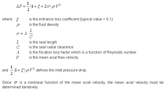
A fundamental relationship between the total axial pressure drop and the mean axial flow velocity is:
The circumferential velocity of the fluid entering the seal is commonly expressed as a fraction of shaft surface speed:

where alpha is the inlet swirl ratio. In Black’s model, the swirl ratio is 0.5. The value can be lower if a swirl break is used. In Childs’ model, the inlet swirl ratio can be varied. It can be seen that inlet swirl has a significant influence on the cross-coupled stiffness and that therefore stability can be improved by reducing the inlet swirl.
Black Model
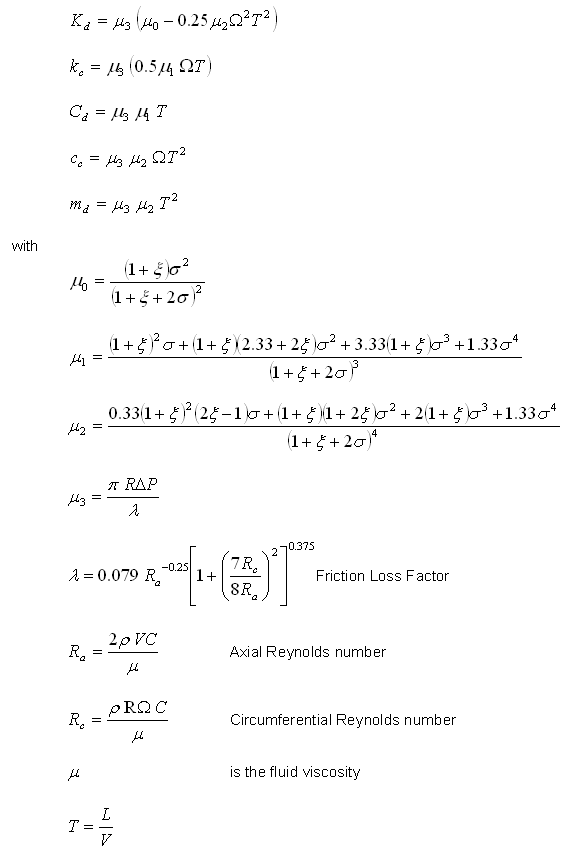
The seal dynamic coefficients based on Black’s model are well documented in references (1,3,4,5) and listed here for reference:
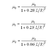
The above parameters are based on short seal solution. The corrected parameters for finite length seal are:
Since the friction loss factor is a function of Reynolds number that is dependent upon the velocity, therefore, an iterative process is needed to solve the mean axial velocity.
Example taken from reference (3) is used to demonstrate this calculation.
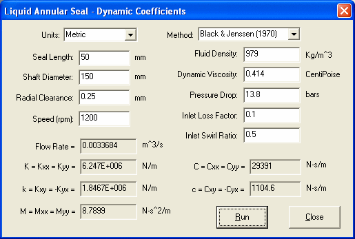
The small differences between DyRoBeS and reference (3) are due to:
1. DyRoBeS uses finite length corrected parameters. However, short seal theory was used in the reference. It is known that short seal solutions tend to overestimate the dynamic coefficients of finite length seals.
2. In reference paper (2), although iteration was used to determine the average axial velocity, however, the initial  was used to calculate the dynamic coefficients. In DyRoBeS, the final converged
  is used in the following calculation.
Childs Model
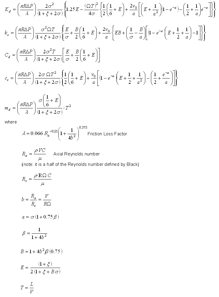
Childs formulated the seal dynamic coefficients based on Hirs’ lubrication equation. The fluid inertia terms are included in the momentum equations and the inlet swirl is also included. The short seal theory is used. The coefficients are summarized in the following:
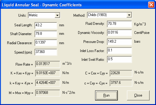
An interstage seal of the High Pressure Hydrogen Turbopump (HPFTP) of the Space Shuttle Main Engine (SSME) used in reference (2) is presented below.
For an inlet swirl ratio of 0.5, that is, the inlet circumferential velocity is a half of the surface speed, the results are listed below.
For uo = 0, the results are listed below:
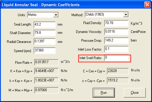
Note that in reference (2),  .
.
The DyRoBeS results are in good agreement with the results of the reference (2).
Data input under Bearing Tab
The seal dynamic coefficients can be calculated internally when performing the rotordynamic analyses. Due to the similarity with bearing data, the seal data are entered under the Bearing tab. A brief description of the data input is listed below:
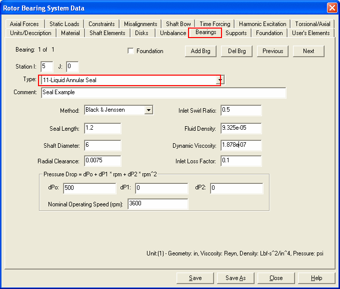
There are two methods provided in DyRoBeS: Black and Jenssen, and Childs (1983). Typical value for the Inlet Swirl Ratio is 0.5; that is, the circumferential velocity of the fluid entering the seal is a half of the shaft surface speed. To improve the rotor stability by decreasing the seal cross-coupling stiffness, a swirl break can be used to lower the swirl ratio. For the Black model, 0.5 is always used. Typical value for the inlet loss factor is 0.1. The inlet pressure drop as the fluid entering the seal is defined by  . Since the total pressure drop (or the pump discharge pressure) is a function of rotor speed, therefore, a second order polynomial is used to calculate the seal total pressure drop for a given speed. The nominal operating speed in this data input page is only used to calculate the seal coefficients for the Critical Speed Analysis since no speed is given in the analysis input. For the Static Deflection and Bearing Loads calculation, seal data are not used. For the Whirl Speed/Stability Analysis, Unbalance Response Analysis, and Transient Analysis, the seal coefficients are calculated for the speeds given in the each Analysis input.
Note:
Two theoretical methods are provided in DyRoBeS to be used in the rotordynamics calculation. In most publications the theoretical models are compared with the test experiments and good corrections were obtained, although certain differences remain. Further differences are evident in the industrial application; therefore, the precaution must be taken while using these coefficients. A tolerance on these calculated coefficients should be applied when the accurate critical speed and stability margins are critical.
References:
1. Black, H. F. and Jenssen, D. N., 1970, Dynamic Hybrid Bearing Characteristics of Annular Controlled Leakage Seals, Proc Instn Mech Engrs, Vol. 184, pp. 92-100.
2.Childs, D. W., 1983, Dynamic Analysis of Turbulent Annular Seals Based On Hirs’ Lubrication.Equaion, ASME Journal of Lubrication Technology, Vol. 105, pp.429-436.
3. Barrett, L. E., 1984, Turbulent Flow Annular Pump Seals: A Literature Review, Shock and Vibration Digest, pp. 3-13.
4. Diewald, W. and Nordmann, R., 1989, Dynamic Analysis of Centrifugal Pump Rotors with Fluid-Mechanical Interactions, ASME Journal of Vibration, Acoustics, Stress, and Reliability in Design, Vol. 111, pp.370-378.
5. Corbo, M. A. and Malanoski, S. B., 2003, Pump Rotordynamics Made Simple, Proceeding of The 15th International Pump Users Symposium, pp. 167-204.
Copyright © 2014-2017