Natural Catenary (Gravity Sag) Analysis
This option performs optimization procedure to find the optimal bearing elevations such that the bending moment and/or shear force due to rotor weight (gravity sag) at coupling station are minimized. For a large turbine-generator system, the moment and force at coupling station, or near coupling location can experience large moment (stress) during startup. Therefore, at the construction of a turbine-generator system, the level of each bearing-center is adjusted (elevated) to minimize the bending moment and shear force at each coupling or locations where the potential failure may occur.
Ideally, the weight of each rotor should be supported entirely by its own bearings. The ideal bearing reactions are therefore equal to the bearing reactions present when the rotors are uncoupled. When the weight of each rotor is supported by its own bearings, the resulting shape of the full-shaft-line caused by the elevations of the bearings is often called Catenary Curve. Please note that the term of catenary used here has little to do with the catenary defined in mathematics or civil engineering due to the complexity of the rotor configurations.
Caution must be taken when performing this task. Misalignment of the bearings will eliminate the high stress at or near couplings during the initial start up. However, this rotor bow also creates a synchronous excitation in addition to the mass unbalance excitation.
For each shaft supported by two bearings, the catenary curve can be obtained by the following procedure which will result in the rotor static weight of each rotor being supported extirely by its own bearings. An example is used here for illustration purposes:

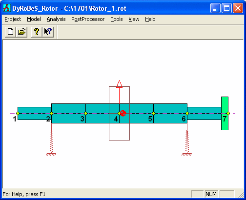
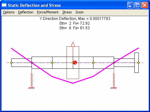
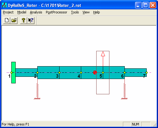
Step 1. Calculates the bearing reactions of the uncoupled rotor due to rotor weight only using Analysis Option 1 – Static Deflection and Bearing Loads.
Rotor 1
Rotor 2
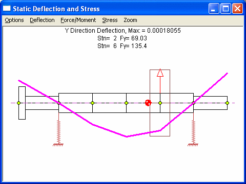
Note that the summation of 2 bearings reaction forces is the rotor static weight.
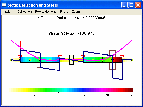
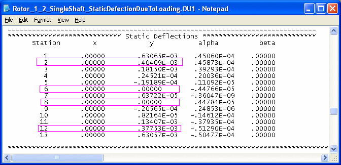
Step 2. Apply this bearing reaction forces on the combined rotor. Note that in this step, since the rotor is unconstrained, the solution is possible only after rigid body motion is eliminated. Since the rotor has translational and rotational motions for each plane, we will need at least two constraints. Most common is to constrain the displacements at two bearings near coupling, in this case, stations 6 and 8. Or, one may consider to restrict the displacement and slope at coupling. Both results from the Analysis Option 1 - Static Deflection and Bearing Loads are shown below:
Case 1 – Fix the displacements at bearings – stations 6 & 8.
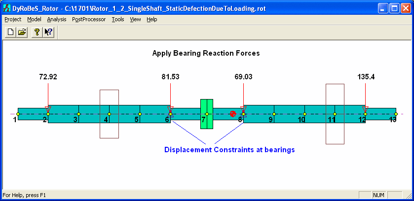
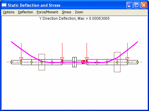
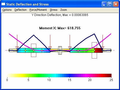
Case 2 – Fix the displacement and slope at coupling – station 7
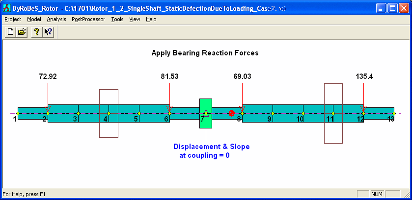
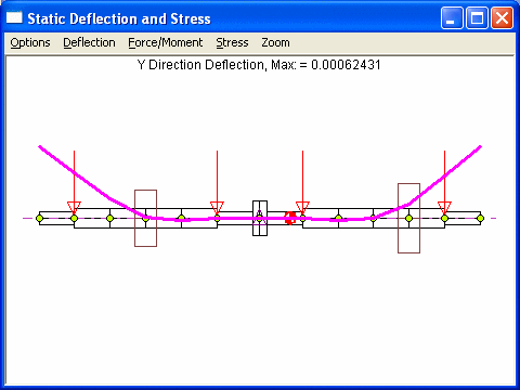
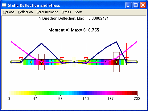
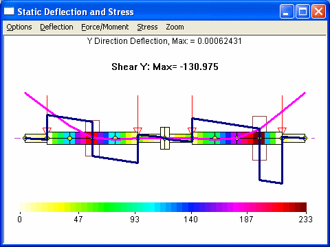
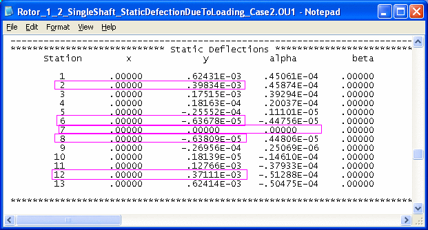
Note that both cases yield nearly identical results in the deflection curve, moment, force, and stress. However, case 1 needs to raise 2 bearings at station 2 and 12 only. But case 2 needs to change the bearing elevations for all 4 bearings, which may not be so desirable, although changes in bearings at stations 6 and 8 are extremely small.
The catenary (gravity sag) analysis provided in DyRoBeS utilizes the optimization techniques to find the optimal elevations for the selected bearings with specified upper and lower bounds such that the moments, and/or forces, and/or slopes at selected stations (may be couplings, bearings, or the weakest link locations) are minimized. One can also use the weighting factors to enhance their objective in moment, or force, or slope.
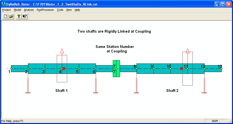
In this same example, let us model the rotor system in 2 shafts, as shown below. Note that if the system is modeled as a single shaft, same result can be obtained.
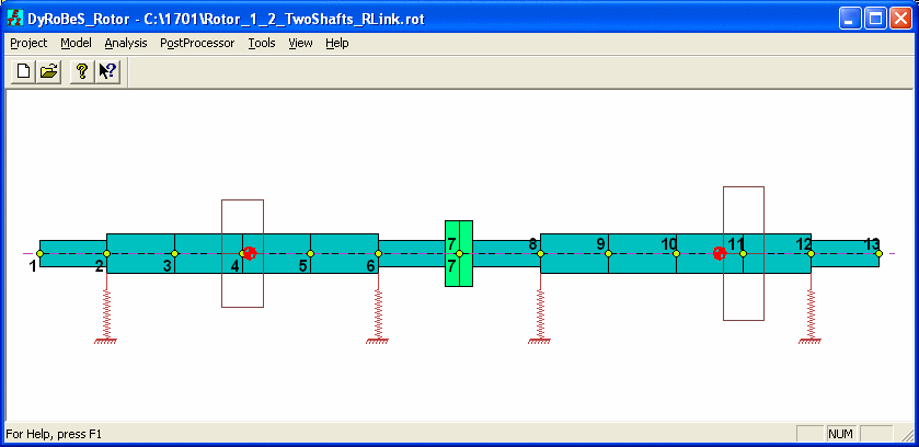
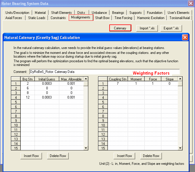
The initial guess values and objective are defined under Misalignment Tab – Catenary button as shown below. It shows that at bearing stations 2 & 12, the initial guess values are 0.0003 inches and maximum allowable values are 0.001 inches. At bearing stations 6 and 8, the initial values are zero and the maximum allowable values are also zero. It indicates that these two bearings are not the design variables and their elevations will not be changed. Coupling station 7 is specified such that the moment and force are minimized. Note that any station or stations can be used to minimize their moments and/or force, and/or slope.
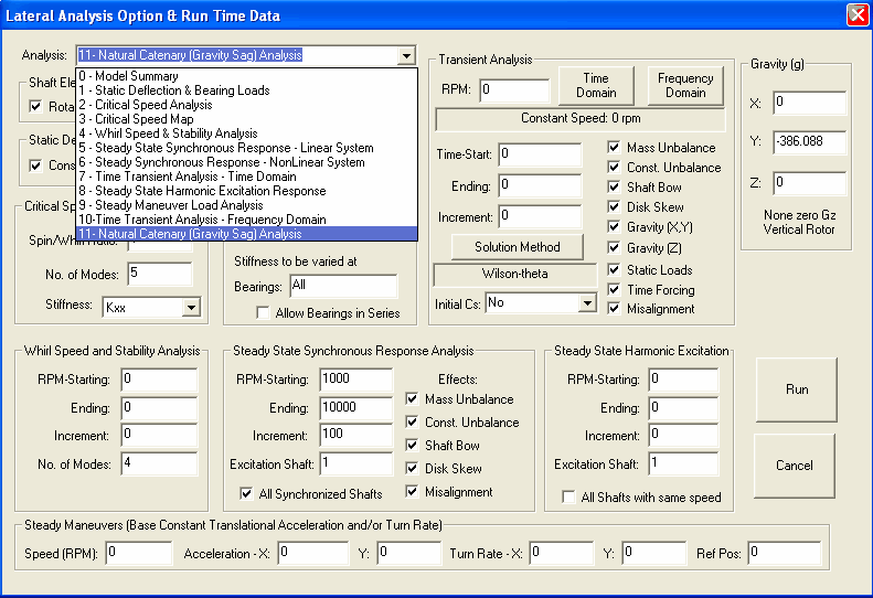
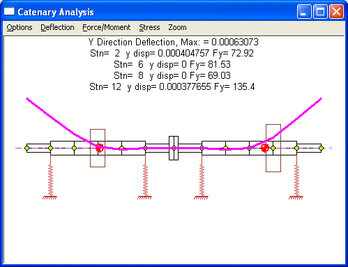
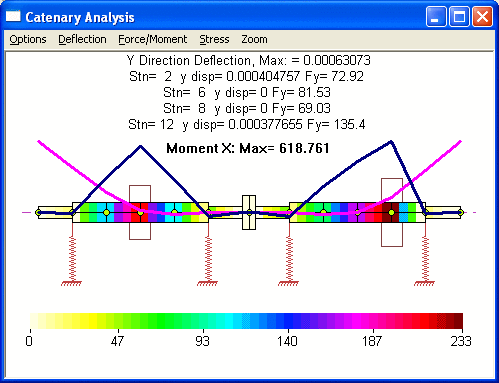
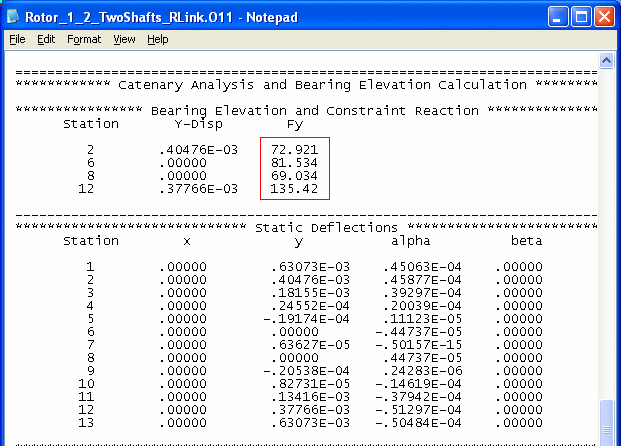
The analysis option is 11 – Natural Catenary (Gravity Sag) Analysis. Once this analysis option is selected, the program will perform the optimization procedure. The results can be viewed just like the results from the Analysis Option 1 – Static Deflection. The final converged results are shown below. It shows that the program converged to the bearing elevations extremely close to the results from Case 1 studied above using manual procedure, which is not surprising. Also, by using these bearing elevations, the bearing reaction forces are identical to the bearing forces from the Step 1 of the manual procedure.
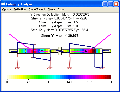
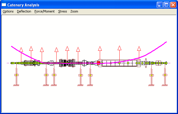
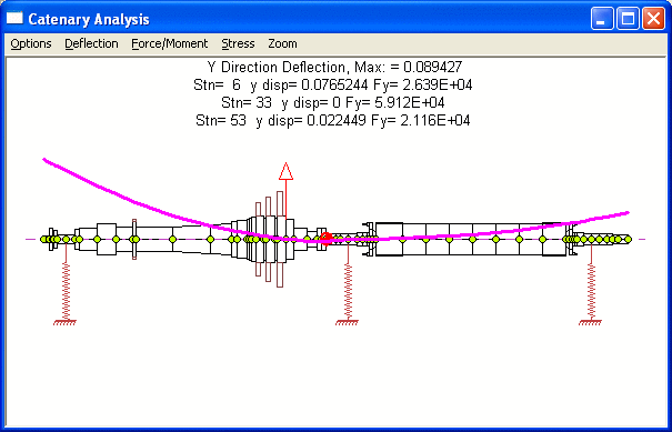
The major benefit of this optimization procedure is not for systems with 2 bearings at each rotor as illustrated in this example, but it is for more complicated systems with many bearings or less bearings for each rotor as shown below.
Copyright © 2014-2017